April 21,2009Measuring Current, Voltage, and Resistance in Series and Parallel Circuits Block D
Purpose: To determine patterns and formulas to predict current, voltage, and resistance in series and parallel circuits.
Procedure: As described in BC Science 9 p. 314-315 + calculations for resistance
Data and Observations:


Questions:
1. In a short paragraph, explain how current and voltage change in a series circuit.
The voltage in a series circuit is different. The first bulb and the second bulb, when their voltages are added together, it forms the voltage of the battery. Also, one of the bulbs have more voltage than the other bulb. Current in a series circuit is the same throughout.
2. In a short paragraph, explain how current and voltage change in a parallel circuit.
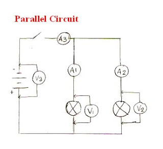
The current in a parallel circuit is different in each area. The wires in which the electrons flows first gets the most current. The middle wire, or A1 above, has the lowest current. The last wire, or A3 above, has the most current. Voltage in a parallel circuit is the same throughout.
3. What do you notice about resistance in series? Do you notice an obvious pattern for resistance
in parallel?
There's a lot more resistance in series than in a parallel circuit. In parallel, I notice that when you multiply the value of V3/A3 by 2, you can almost get the value of V1/A1.
(Actually, I'm not really sure of what I'm writing, but there are my observations.)
Conclusion:
I learned in series circuits that the current stays the same throughout, while the voltage stays the same throughout parallel circuits. Also, here are some patterns that I learned.
In series,
V1 + V3 = V2 or in words, the voltage of two light bulbs equals the voltage of the battery.
In parallel,
A1 x 2 = almost A3 or in words, the current in the middle wire multiplied by two is almost the value of the current near the switch.
The value of V3/A3 multiplied by 2 is almost the value of V1/A1.
Tuesday, April 21, 2009
Measuring Current, Voltage, and Resistance in Series and Parallel Circuits
Posted by Julie Anne at 7:42 PM
Subscribe to:
Post Comments (Atom)

1 comments:
Good circuit diagrams and thoughtful responses in questions and conclusion
10/10
Post a Comment